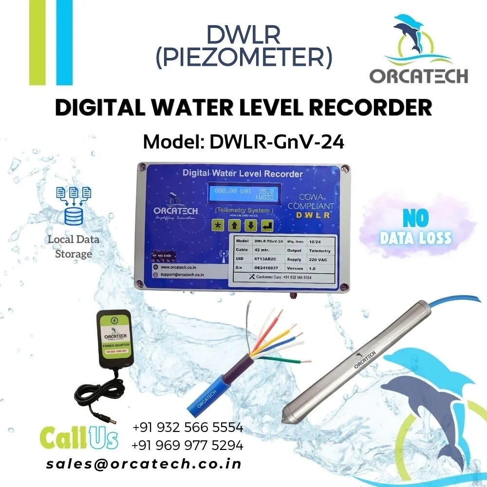
A digital water level recorder measures pressure at a known depth, then converts that reading into a groundwater level tied to a surveyed reference point. By the end, you will know how to build the monitoring point, select and install the sensor, set a defensible logging plan, and verify that the resulting groundwater series is trustworthy.
Key takeaways
- Survey the reference elevation before installing the submerged pressure sensor.
- Record whether results mean depth below ground or groundwater elevation.
- Use a vented or barometric correction method suited to site conditions.
- Test timestamps, interval settings, memory, battery, and data export before acceptance.
What a groundwater level recorder actually measures
A digital water level recorder measures pressure at a submerged sensor, not groundwater elevation directly. Software converts that pressure into water head and ties it to a surveyed reference point, producing either depth to water below ground level or groundwater elevation. It does not measure water volume or pumping rate.
The usual relationship is: groundwater elevation = measuring-point elevation − corrected depth to water.
| Method | What it records | Type of result |
|---|---|---|
| Digital water level recorder | Sensor pressure at programmed time intervals | A time series for continuous groundwater monitoring |
| Manual water-level reading | Water position observed with an electric water-level tape or wetted-tape sounder | One depth measurement at a specific time |
| Digital recorder output | Corrected pressure converted against a fixed datum | Changing depth or elevation between manual checks |
A manual reading is a single observation, while a recorder reveals recovery, recharge, drawdown, and short-lived fluctuations between site visits. Compare manual readings at deployment, retrieval, and during operation to detect sensor drift, a shifted suspension point, clock error, or failed barometric correction.
In a pumping well, the recorded change can represent local drawdown, pump cycling, turbulence, or vertical flow rather than formation-wide groundwater conditions. Use a dedicated observation well when the objective is regional groundwater level.
Build the monitoring point before installing the sensor
A meaningful record starts with a fixed reference point, not the logger’s programmed zero. Choose a borewell or piezometer that represents the formation you need to monitor; a pumped production well can record pump drawdown, turbulence, or vertical flow instead of regional groundwater head.
Confirm the screened interval and its relation to nearby aquifers and pumping zones.
1. Define the measuring point: mark the exact casing rim, notch, or access tube lip from which every manual depth-to-water reading will be taken. Protect it with a stable cover and record its elevation against a named survey datum.
2. Survey the site and record coordinates, ground elevation, casing elevation, borewell diameter, total depth, and the screened interval. Do not substitute ground elevation for the measuring-point elevation; that error shifts every reported water level.
3. Measure and document the installation depth from the measuring point to the pressure sensor. Record the cable reference mark, sensor serial number, logger zero, and the planned cable anchor so a later suspension change cannot look like an aquifer response.
4. Check that the casing is open and stable, and install an access tube or centraliser where needed to keep the sensor away from pumps, joints, and the casing wall. Secure the cable without allowing it to stretch, slip, or rub against sharp edges.
5. Take an independent electric-tape reading after the sensor stabilises. Record the date, time zone or UTC convention, water temperature if available, sensor depth, barometric or vent arrangement, and the initial depth to water; retain raw pressure and all survey records with the installation file.
Convert pressure into a defensible water level
Convert the pressure reading into water head, then tie that head to the surveyed measuring-point datum. The reported elevation is usually measuring-point elevation minus corrected depth to water; a pressure transducer does not measure groundwater elevation directly.
An absolute pressure sensor records water pressure plus atmospheric pressure. Apply barometric compensation using a separate, time-synchronised barometric record from a representative location, or atmospheric changes will appear as false groundwater movement. A vented transducer uses a vented cable to reference atmospheric pressure continuously, but a blocked or wet vent can still create errors.
Water density controls the conversion from pressure to head. The freshwater approximation is about 9.81 kPa per metre of water at standard conditions. Saline, brackish, highly mineralised, or temperature-variable groundwater needs a density value suited to the site; using freshwater density can produce a material elevation error.
Choose a pressure range that covers the greatest possible submergence, not just the static level. Installation depth, pumping drawdown, recharge, density changes, and pressure surges can overrange the sensor, and post-processing cannot reliably restore an overrange reading.
Do not confuse resolution with accuracy. A display resolving 1 mm does not prove 1 mm accuracy; include temperature effects, range error, drift, compensation error, datum error, and installation effects in the uncertainty.
Retain the evidence needed to defend the result:
- Raw pressure and barometric data
- Calibration and compensation parameters
- Manual-check results
- Sensor serial number and installation depth
- Measuring-point datum, time convention, and every edit
A sensor installed deeper has more pressure head but less range margin. Record its depth and reference elevation precisely; mixing depth-below-casing with elevation-above-datum corrupts the series.
Choose the logging interval and protect the data series
Choose the logging interval from the shortest groundwater response you need to see, not from battery life. Use minutes for aquifer testing, pumping recovery, or recharge pulses; a daily interval suits seasonal groundwater monitoring only when shorter events do not matter.
Confirm whether the instrument samples instantaneously or stores or transmits an average, because averaging can hide peak drawdown. Check memory, battery demand, telemetry cost, and deployment duration before deciding.
| Purpose | Interval decision | Failure if mischosen |
|---|---|---|
| Seasonal groundwater monitoring | Match the trend resolution required | Short pumping or recharge responses disappear |
| Aquifer testing | Resolve the test steps and recovery curve | Drawdown and recovery parameters become unreliable |
| Pumping recovery | Continue short intervals until the level stabilises | Early rebound is missed |
Validate the series against manual measurements at deployment start, during operation, and at retrieval. Compare readings at matching timestamps, using the same measuring-point datum and time zone; record the logger clock against a reference clock before and after deployment.
Investigate any offset that changes with time, which indicates clock drift, sensor drift, a shifted suspension point, wrong installation depth, or failed barometric compensation. A nonvented pressure sensor also needs a time-synchronised barometric record.
Retain raw pressure, barometric data, calibration and compensation parameters, manual results, sensor serial number, installation depth, datum, clock convention, and every edit. If the recorder sits in a pumped well, treat the record as local well hydraulics; use an observation well when formation head is the objective.
Specify, install, and accept the complete monitoring system
Require a complete measurement chain, not only a recorder and factory certificate. The supplier must state sensor range, accuracy, resolution, temperature effects, drift, barometric-compensation method, power autonomy, memory capacity, telemetry failure behaviour, and export format.
Require raw pressure, barometric data, calibration parameters, compensation settings, serial number, installation records, manual checks, edits, and every UTC timestamp in the data package. Ask Orcatech Enterprises—or any supplier—to identify which values remain available when communications fail.
Record the installation independently of the logger’s programmed zero. The handover sheet must include:
- Measuring-point datum and its survey reference
- Sensor installation depth, cable length, wellhead reference, and installation date
- Sensor serial number, pressure range, calibration certificate, and firmware version
- Barometric sensor location or vent path, plus the time zone and UTC timestamp convention
- Pump status, well construction, screened interval, and any reason the well may show local drawdown rather than formation head
Run a documented field acceptance test before treating the series as groundwater data. Compare the recorder with an independent electric-tape reading, confirm the measuring-point elevation and sensor depth, and verify the barometric record or vent path.
Check clock offset against a known UTC source, inspect the first record for implausible steps and flatlining, and trigger a known level change if safe. Record discrepancies, corrections, and acceptance signatures; a factory calibration certificate alone does not prove that the installed system is ready.
Related products
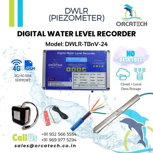
 | Digital Water Level Recorder (DWLR) ₹51330 Digital Water Level Recorder, Telemetry with Local Data Storage, Grid Operated, Cloud Application, Digital Reporting View product → |
 | Digital Water Level Recorder (DWLR) ₹62304 Digital Water Level Recorder, Telemetry with Local Data Storage, Grid Operated, Cloud Application, Digital Reporting View product → |
Frequently asked questions
What does a digital water level recorder actually measure?
It measures pressure at a submerged sensor. Software converts that pressure into water head, then references it to a surveyed point to calculate depth to water or groundwater elevation.
How do you convert pressure into a defensible groundwater level?
Use the sensor’s calibration data, apply the correct water-density and atmospheric-pressure corrections, and reference the result to a surveyed datum and measuring point.
How often should a groundwater level recorder log data?
Choose the interval from the groundwater process you need to observe: use shorter intervals for pumping or recharge events and longer intervals for slow seasonal changes. Confirm the logger can store the series for the full deployment.
What should you check before accepting a monitoring system?
Check the monitoring point, sensor depth, reference elevation, clock, logging interval, battery, memory, communications, calibration records, raw data export, and recovery procedure.
Related product
 | Digital Water Level Recorder (DWLR) ₹83544 Digital Water Level Recorder, Telemetry with Local Data Storage, Battery Operated, Cloud Application, Digital Reporting View product → |