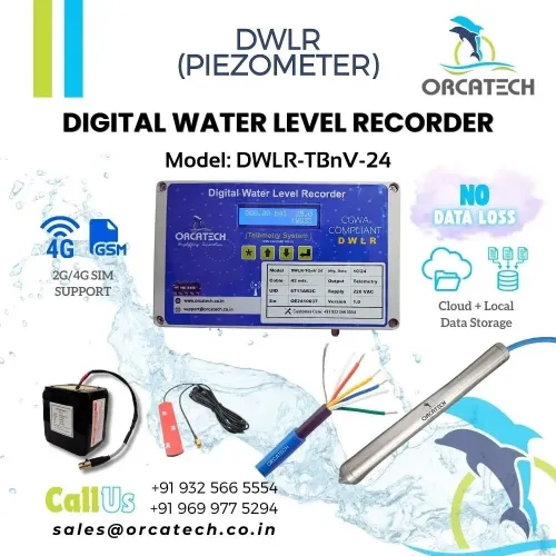
A DWLR produces a pressure time series, but accurate groundwater monitoring depends on more than the displayed number. By defining the measured quantity, installing the sensor against a fixed datum, choosing suitable sampling and power settings, and checking the record against independent measurements, you can produce groundwater data that remains comparable over time.
Key takeaways
- Convert pressure readings using atmospheric compensation and a fixed measuring datum.
- Choose sensor range and sampling intervals that capture the expected groundwater fluctuations.
- Check timestamps, gaps, drift, and recovery data after outages or communication failures.
- Specify battery life, telemetry, storage, and export formats before deployment.
Define What the DWLR Measures Before You Compare Readings
A DWLR records pressure, not depth directly. The transducer senses water pressure, and an absolute-pressure unit also senses atmospheric pressure; a vented unit uses a vent tube to apply atmospheric pressure to the reference side. Report the DWLR measurement only after stating how that pressure became a groundwater quantity.
| Report as | Definition | Main caution |
|---|---|---|
| Depth to groundwater | Vertical distance from the measuring point down to the water surface | State the sign convention and reference point |
| Water-level elevation | Water-surface height relative to a named vertical datum | Requires the measuring-point elevation and sensor geometry |
| Hydraulic head | Pressure expressed as an equivalent water-column height relative to a datum | Water density affects conversion; salinity and temperature matter in brackish or industrial water |
| Change in level | Rise or fall relative to a stated baseline and time | It does not replace an absolute elevation |
Before comparing readings, record these items:
- Well identifier, measuring-point elevation, vertical datum, sensor elevation or cable reference, and the depth-to-groundwater sign convention.
- Whether the logger is absolute or vented, and which barometric record supplied compensation. Synchronize timestamps and use a barometer representing the well location.
- An independent electric-tape or steel-tape reading from the same measuring point during installation and servicing. Adjust for the sensor-to-reference elevation before diagnosing sensor error.
Without this metadata, a precise pressure time series cannot reliably become comparable water-level elevation.
Install the Sensor Against a Fixed Measuring Datum
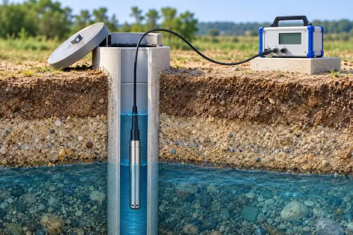
A fixed reference point turns a DWLR reading into a repeatable groundwater measurement. Choose a marked point on the well casing, not a replaceable cap, and survey its elevation against a named vertical measuring datum. Keep the point physically unchanged after installation.
Record these details before lowering the sensor:
- Well identifier and coordinates.
- Measuring datum and reference-point elevation.
- Sensor elevation, or the fixed cable mark that defines it.
- Sign convention, such as positive depth measured downward from the reference point.
- Installation date, cable length, logger serial number, and sensor position relative to the screened interval.
Secure the cable so the transducer cannot rise, sink, or swing against the casing. Place it below the lowest expected water level but away from a pump intake, strong screen inflow, or turbulent discharge; those locations record local disturbance rather than representative head.
Protect the cable and logger from abrasion, flooding, and tampering, and use a vented installation with a dry, protected vent path when the instrument requires atmospheric compensation.
At installation and every service visit, measure water level with an electric tape or steel tape from the same reference point. Convert that reading using the sensor-to-reference distance before judging the logger. A raw pressure-derived value and an unreferenced tape reading are not comparable.
Record any cap replacement, moved cable mark, altered reference point, or resurvey to a different datum as a metadata event. Apply the resulting datum correction to the time series; never treat the step change as groundwater movement.
Match Sensor Range and Sampling Interval to the Groundwater Signal
Choose the pressure-sensor technology and range from the signal you need to detect, not from the well’s commissioning reading. A vented pressure transducer passes atmospheric pressure through a vent tube; a non-vented pressure sensor measures absolute pressure and requires a separate barometric record.
| Technology | Atmospheric reference | Best fit |
|---|---|---|
| Vented pressure transducer | Vent tube applies local air pressure to the reference side | Long-term wells with protected, dry venting |
| Non-vented pressure sensor | Separate barometer supplies atmospheric compensation | Flood-prone installations or sealed cable systems |
| Water-level transducer | Reports pressure-derived level after compensation and datum conversion | Sites where pressure records must become comparable water levels |
Select the smallest range that covers the highest possible hydraulic head, including artesian rise and pumping drawdown. A ±0.1% full-scale specification on a 30 m range equals ±0.03 m before other errors; a larger range increases absolute error. Check both accuracy and resolution against the smallest change you need to identify.
Set the sampling interval from the fastest phenomenon of interest and the well’s response time. Seasonal trend monitoring needs less frequent readings, while pumping cycles, barometric responses, slug-test recovery, and recharge pulses need shorter intervals. Unnecessarily short intervals consume battery, memory, and telemetry capacity.
Store timestamped raw pressure, compensated level, temperature, and barometric values when available. Synchronize the barometer and logger clocks, and place the barometer near the well; a distant or unsynchronized record can turn air-pressure differences into false groundwater changes. Compare the output with an electric tape at the same reference point during installation and servicing.
Verify the Record and Recover Data After Measurement or Network Errors
A logger reading that diverges from a manual water-level measurement does not prove sensor failure. Repeat the comparison from the same measuring point, apply the documented sensor-to-reference elevation, and check whether the difference persists across two or more measurements.
A persistent offset indicates a calibration problem; a gradual change indicates sensor drift. Perform a field calibration check against an electric or steel tape, record the date, reference point, logger value, independent value, temperature, and calculation, then flag affected observations. Do not overwrite raw files.
Store the corrected series separately with the adjustment and its start time.
Use this recovery sequence:
- During a telemetry outage, preserve the logger’s local file, download it before resetting the instrument, and reconcile transmitted records against local timestamps to remove duplicates, restore missing rows, and place late packets in order.
- Check clock time against a known standard during every service visit. Record the time zone and clock offset; correct drift, daylight-saving shifts, battery-replacement changes, and unsynchronized records before comparing peaks.
- For absolute-pressure units, verify that the barometric record covers the well location and has synchronized timestamps. A distant or misaligned barometer can turn atmospheric pressure changes into false groundwater fluctuations.
- Mark gaps, estimated values, and corrected readings in separate fields. Retain the original value, correction method, operator, and revision date.
After recovery, compare the adjusted series with manual water-level measurements and nearby wells. Investigate any unexplained step change before treating it as a groundwater event.
Specify Power, Uptime, and Data-Handling Requirements Before Deployment
Require a worst-case autonomy calculation and a recovery plan before approving a DWLR deployment. A headline battery life figure is meaningless unless it states the sampling interval, transmission frequency, signal strength, temperature, and battery condition used to obtain it.
1. Ask for the operating voltage, peak modem current, expected battery life, memory capacity, and backup power arrangement. Require the calculation for the longest communication outage, not just normal operation.
2. Request operating and storage temperature limits, enclosure ingress rating, flood protection, humidity limits, and surge or lightning protection. Test the enclosure and battery plan against the site’s extreme temperature, not the supplier’s office conditions.
3. Confirm cellular coverage at the well, including the carrier, network bands, antenna position, and signal-strength record. Require timestamped local logging during cellular coverage outages, automatic retransmission, duplicate-packet handling, and a documented export format such as CSV.
4. Demand evidence of clock accuracy, time-zone handling, cloud retention, and how partial or misordered transmissions are reconciled with the logger’s stored record. Ask for a sample download, not a screenshot.
5. Obtain the service schedule, battery replacement procedure, calibration or verification records, spare-parts availability, and outage-recovery test results. For a proposal from Orcatech Enterprises, request these details for the exact configuration, including grid failure and battery depletion scenarios.
Related products
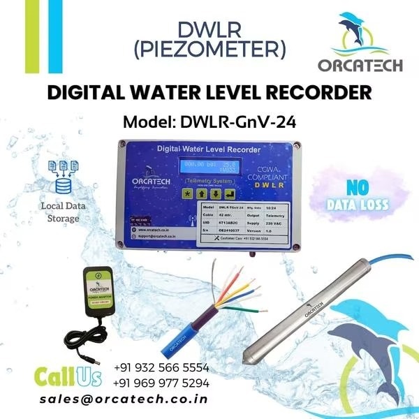
 | Digital Water Level Recorder (DWLR) ₹51330 Digital Water Level Recorder, Telemetry with Local Data Storage, Grid Operated, Cloud Application, Digital Reporting View product → |
 | Digital Water Level Recorder (DWLR) ₹62304 Digital Water Level Recorder, Telemetry with Local Data Storage, Grid Operated, Cloud Application, Digital Reporting View product → |
Frequently asked questions
What does a DWLR measure?
A DWLR measures water pressure. Convert that pressure into groundwater level using atmospheric compensation and a stated reference datum.
How should you install a DWLR sensor?
Install the sensor at a known position relative to a fixed measuring datum, then record the installation depth and datum elevation.
How do you choose a DWLR sensor range and sampling interval?
Select a pressure range that covers the expected water-level change without sacrificing resolution, and choose an interval that captures the groundwater signal.
How can you verify a DWLR record after an error?
Check timestamps, missing intervals, pressure spikes, sensor drift, battery status, and manual water-level observations before accepting the record.
What data and power requirements should you specify before deployment?
Define uptime, battery duration, telemetry coverage, local storage, timestamp rules, data exports, and recovery procedures before installing the network.
Related product
 | Digital Water Level Recorder (DWLR) ₹83544 Digital Water Level Recorder, Telemetry with Local Data Storage, Battery Operated, Cloud Application, Digital Reporting View product → |